Test an external device
Each workflow uses one Maestro workspace and one external device. Connect the PC to the device through a compatible serial interface. In Maestro, Connected means the COM port is open. Use a request and its reply to verify that Modbus communication works.
1. Test an external slave with Maestro Master
- Choose Open master. Select the COM port connected to the slave, such as a drive or meter. Match its baud rate, data bits, parity, and stop bits, then select Connect.
- Choose New watch and select the device’s slave address. Use Add attached watch to keep the values in a tab inside Master, or Open separate watch to view them in a movable window. Create a watch for each slave address you want to monitor.
- For a holding-register read, open Holding registers in that watch, choose Add registers, and enter the protocol start address and count you plan to read. A watch displays matching read replies. Opening it does not send requests, and the initial zeros are placeholders.
- Use the device’s register map to choose a supported read and a readable address. For a holding register, select 03 Read holding registers in Requests. Enter the device’s slave address, the protocol start address, and the count, then select Send. If the manual lists 4xxxx register references, check how they map to protocol addresses.
- In Communication monitor, check for the TX request and a successful RX reply. In the watch, compare the updated value with a known device reading. To refresh the values, send the read again or add it to the request queue and start the queue.
2. Test an external master with Maestro Slave Simulator
- Choose Open simulator. Select the COM port connected to the external master, such as a PLC. Match the master’s baud rate, data bits, parity, and stop bits. Set the Slave address to the address the master will query (001 in this example), then select Connect.
- Prepare a known reply in the simulator. For this example, use Holding registers → Add to create one register at decimal address 10. Enter 1234 in its Decimal field. If the master already has a configured request, prepare the address and range it uses.
- Send the read from the external master. For the example, send FC03 to slave 1, start address 10, count 1. Confirm the request and reply in the simulator’s communication monitor, then check that the external master received 1234.
Practice with two Maestro workspaces
For practice on one PC, Maestro’s master sends requests and its simulator replies. The two windows still need separate COM ports joined by a working serial link. Use connected adapters or a virtual null-modem pair. The integer and floating-point exercises below use this setup.
Connect the two workspaces
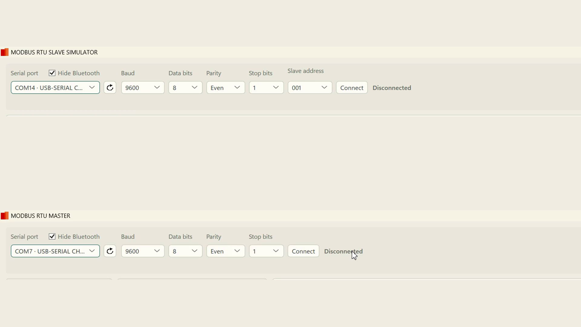
In Modbus RTU Maestro 1.1.0, choose Open simulator and Open master. Opening both windows does not create a connection. Select one end of the serial link in each workspace. The example uses COM14 for the simulator and COM7 for the master. Set both to 9600 baud, 8 data bits, Even parity, and 1 stop bit. Set the simulator’s slave address to 1 and select Connect in both workspaces.
Set three known values
In the simulator, open Holding registers and choose Add. Enter decimal start address 10 and count 3. Set the Decimal values at addresses 10, 11, and 12 to 110, 120, and 130. The first card says Register 0011, but its Address is 0010. Use the Address field for the request.
Prepare the attached watch
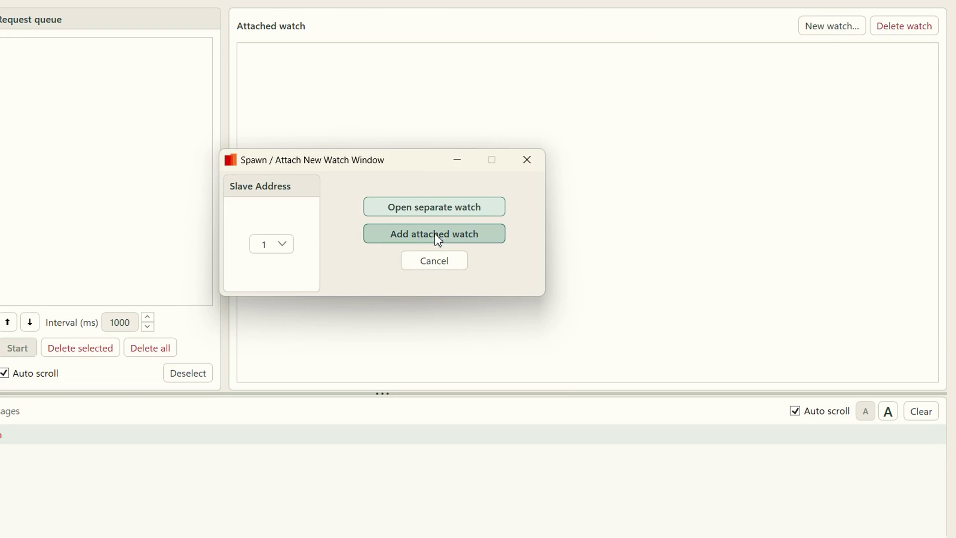
In the master, choose New watch, select slave 001, and choose Add attached watch. In that watch’s Holding registers tab, choose Add registers and enter decimal start address 10 and count 3. The initial zeros are placeholders until the first successful read.
Send the holding-register read
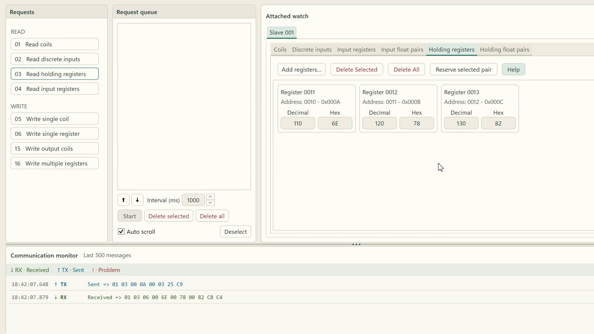
In Requests, choose 03 Read holding registers. Select slave 001, enter decimal starting address 10 and count 3, then choose Send. Check for a TX request and an RX reply in the Communication monitor. The attached watch should show 110, 120, and 130 in order.
Open full-size screenshot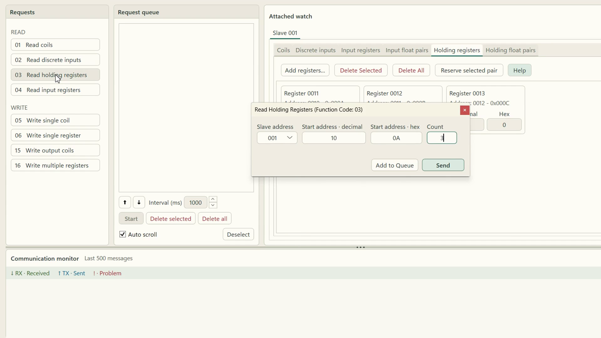
The request in step 4. Enter 10 in the decimal address field. Open full-size screenshotThe result after Send. Decimal addresses 10, 11, and 12 return 110, 120, and 130.
Read a 32-bit floating-point value
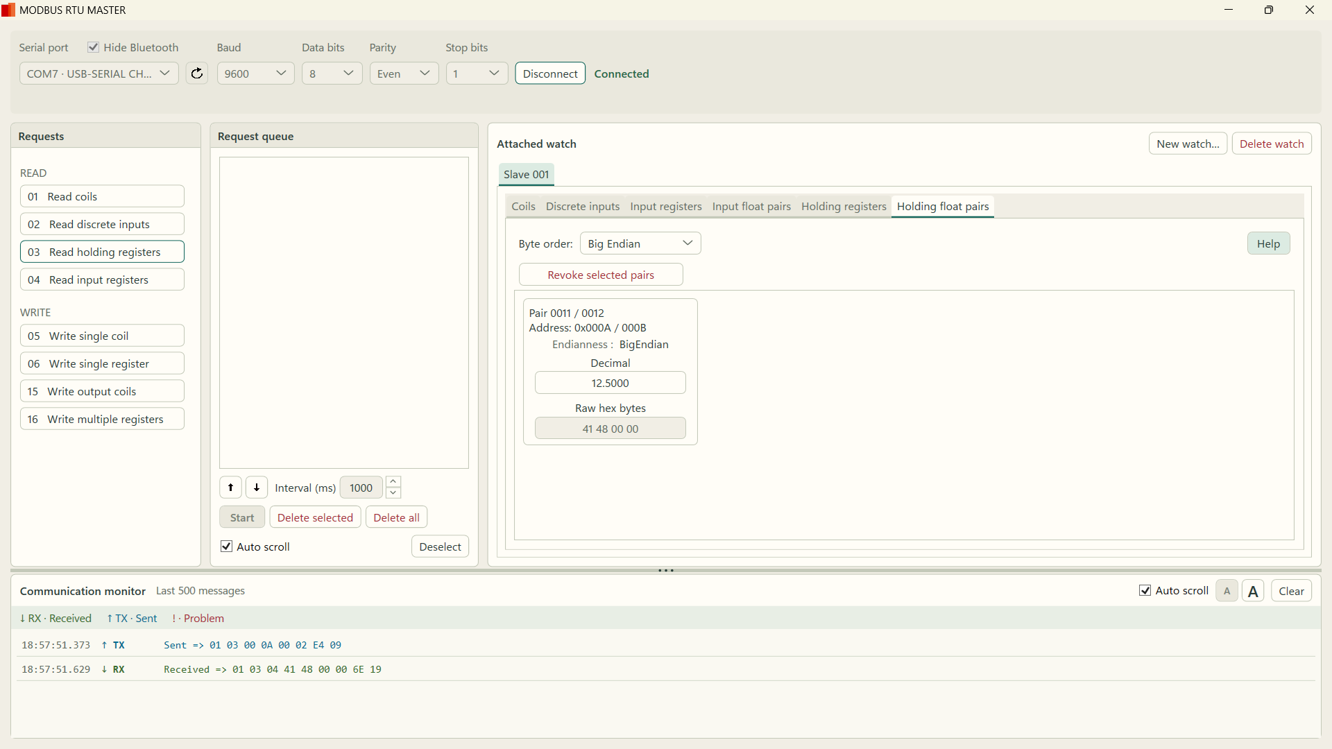
A 32-bit IEEE 754 float uses two consecutive 16-bit holding registers. For this example, 12.5 is stored as 0x4148 at address 10 and 0x0000 at address 11, with the high word first.
- In the simulator’s Holding registers tab, set the Decimal values at addresses 10 and 11 to 16712 and 0.
- In the master’s attached watch, select the cards at addresses 10 and 11 together and choose Reserve selected pair. Open Holding float pairs and set Byte order to Big Endian.
- Send another FC03 request to slave 001, starting at decimal address 10 with count 2. The expected value in Holding float pairs is 12.5. For another device, use the byte order specified by its documentation.
Troubleshoot the practice reads
- Port missing or busy. Check that Windows sees both ports and that each port is open in only one workspace or program.
- TX without RX. Check the connection between the ports, both serial settings, and slave address 1. Connected means the port opened. Look for an RX reply to confirm communication.
- Wrong values or a Modbus exception reply. Confirm FC03 and decimal start address 10. Use count 3 for the first read or count 2 for the float. Make sure the simulator and attached watch cover the requested range and the same slave address. For the float, check that both addresses are reserved as one pair and Byte order is Big Endian.